Laser Diagnostics and In-Cylinder Flow Control in Internal Combustion Engines
Efficient combustion requires understanding the interaction of air, fuel, turbulence, and wall heat transfer. Our laboratory uses a single-cylinder optical engine with viewing windows to resolve flame and flow structures in time using laser diagnostics and PIV.
OH-PLIF and CH2O-PLIF reveal reacting and preheat regions. Combined with in-cylinder pressure and MEMS heat-flux measurements, they help establish how flow affects combustion rate, stability, and wall heat loss.
1. Why look inside an engine?
In-cylinder flow changes with crank angle. Optical access allows us to follow flames and flow in space and time; pressure and heat-flux measurements connect these images to engine performance.
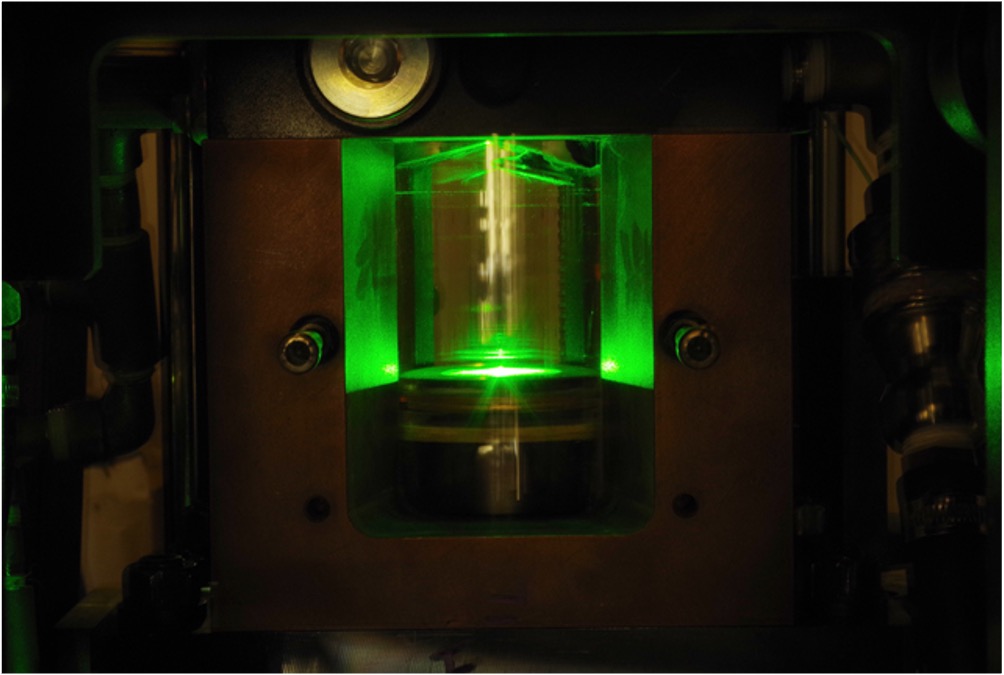
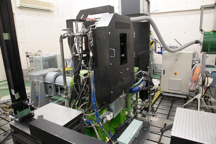
The optical engine shown provides access through the cylinder and piston to observe flame development after ignition. Comparing variations in flame-kernel growth and local extinction under the same operating conditions helps identify the causes of combustion variability.
2. Visualizing flames and flow (OH-PLIF and PIV)
OH-PLIF measures flame structure, while stereo micro-PIV measures the in-cylinder velocity field. Comparing images at corresponding crank angles relates flame growth after ignition to changes in the flow.
Imaging flames with OH-PLIF
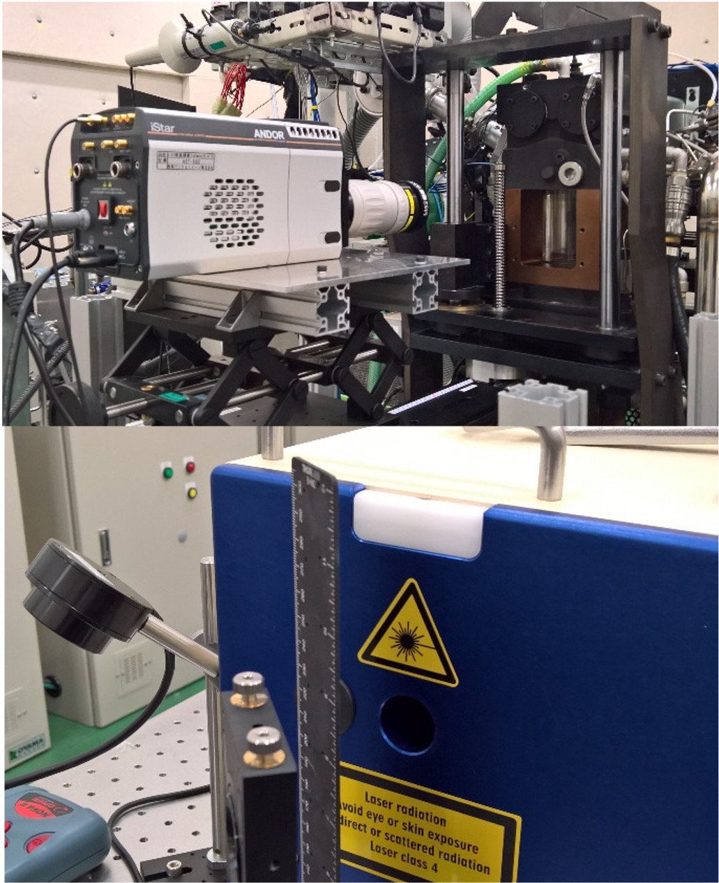
A sheet of ultraviolet laser light enters the combustion chamber, and a camera records fluorescence from OH. Optical filters select the detection wavelengths to reveal the OH distribution in a section of the chamber.
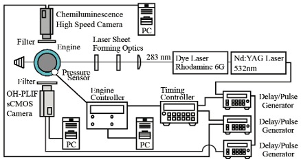
The schematic shows the relative positions of the engine and measurement optics. The ignition location and measurement plane provide reference points for comparing flame development at different crank angles.
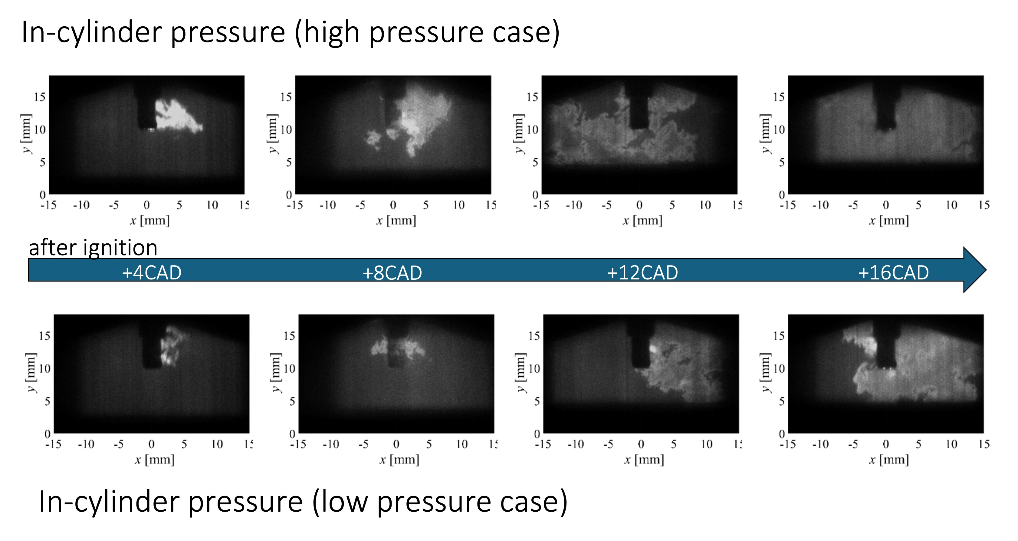
The OH-PLIF images below allow comparisons of flame position and shape after ignition. In-cylinder pressure data help relate the observed flame structures to cycle-to-cycle combustion variability.
Measuring flow with stereo micro-PIV
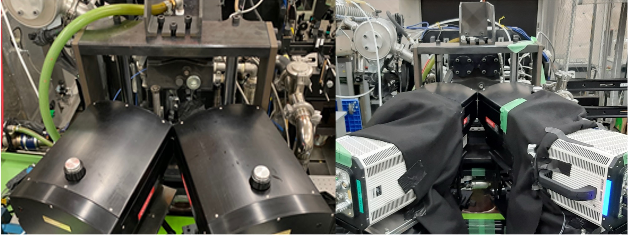
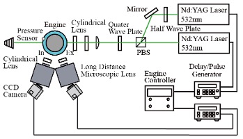
Two cameras observe tracer particles from different directions. Particle-image displacement yields all three velocity components within the measurement plane. The photograph and schematic show the laser, cameras, and engine arrangement.
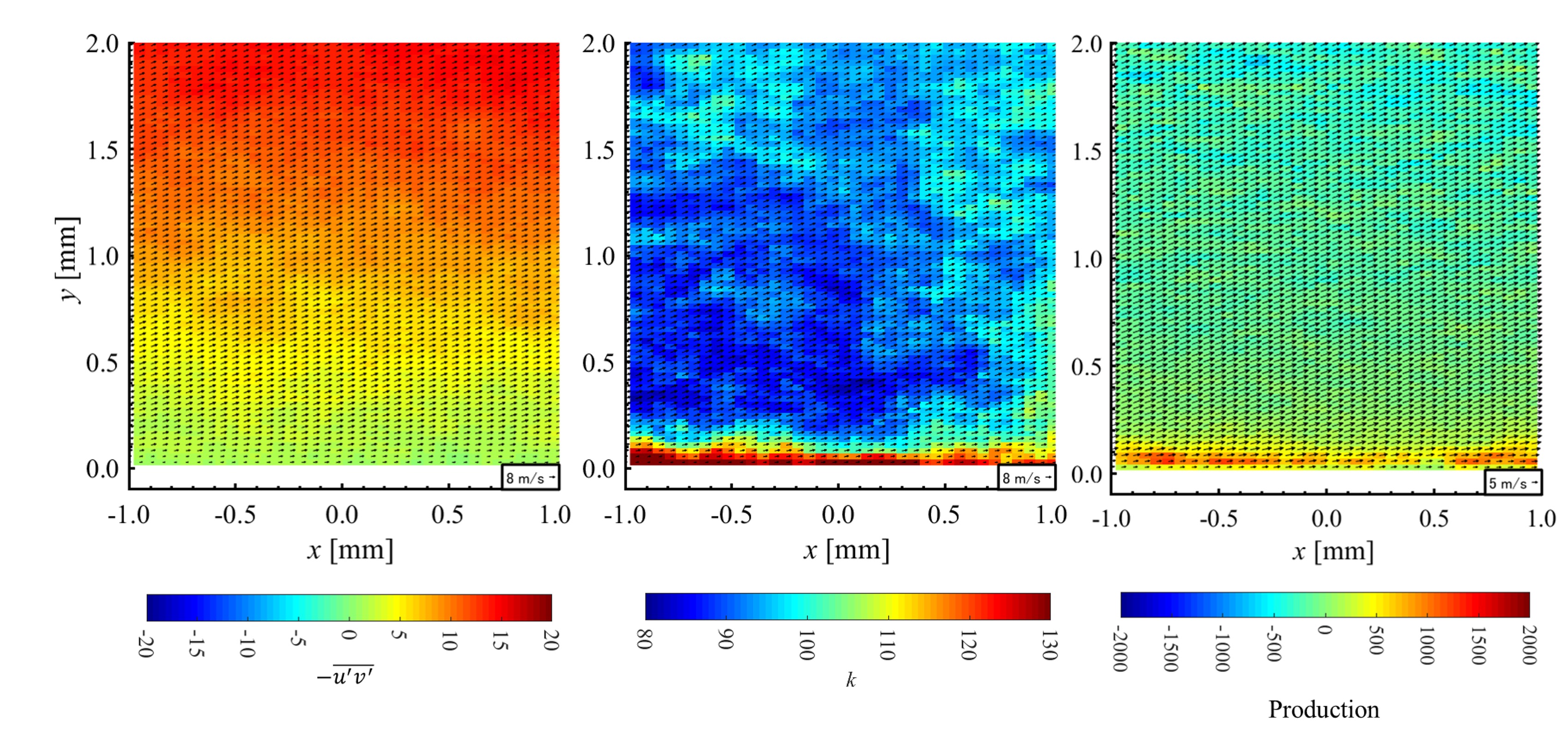
Reynolds stresses, turbulent kinetic energy production, and turbulent kinetic energy derived from velocity fluctuations reveal turbulence intensity and energy transfer from the mean flow. Considering these distributions alongside flame images helps investigate the relationship between flow structures and flame deformation and propagation.
3. Simultaneous OH-CH2O-PLIF
Combining OH and CH2O fluorescence reveals in-cylinder combustion through the distributions of different chemical species. Recording both signals in the same combustion cycle allows spatial relationships to be compared without the ambiguity introduced by images from different cycles.
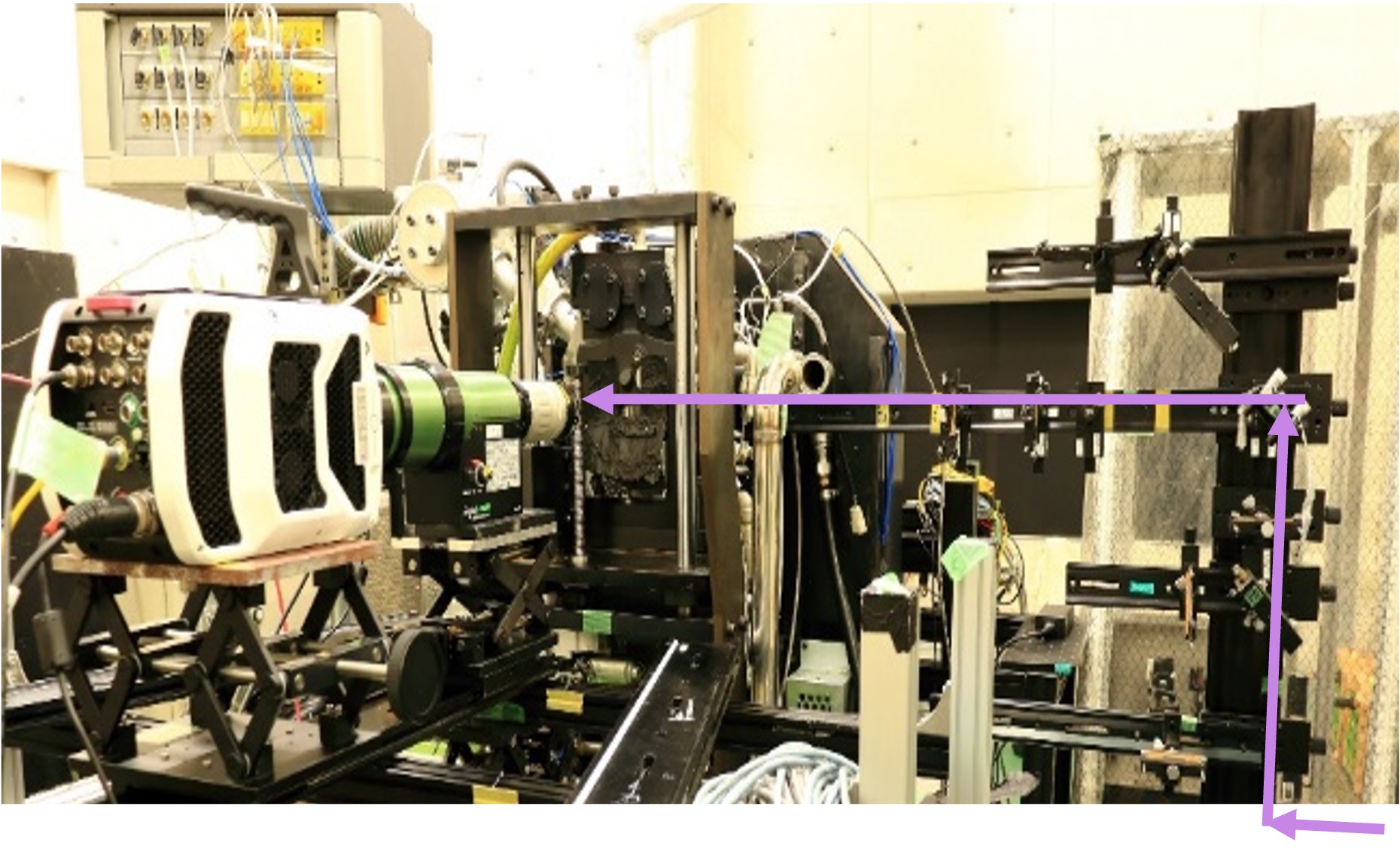
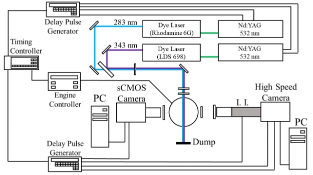
The photograph and schematic show two excitation lasers and their detection systems. Wavelengths and optical filters are selected for OH and CH2O, with acquisition timing referenced to crank angle. Background light and differences between the optical systems must also be considered when comparing images.
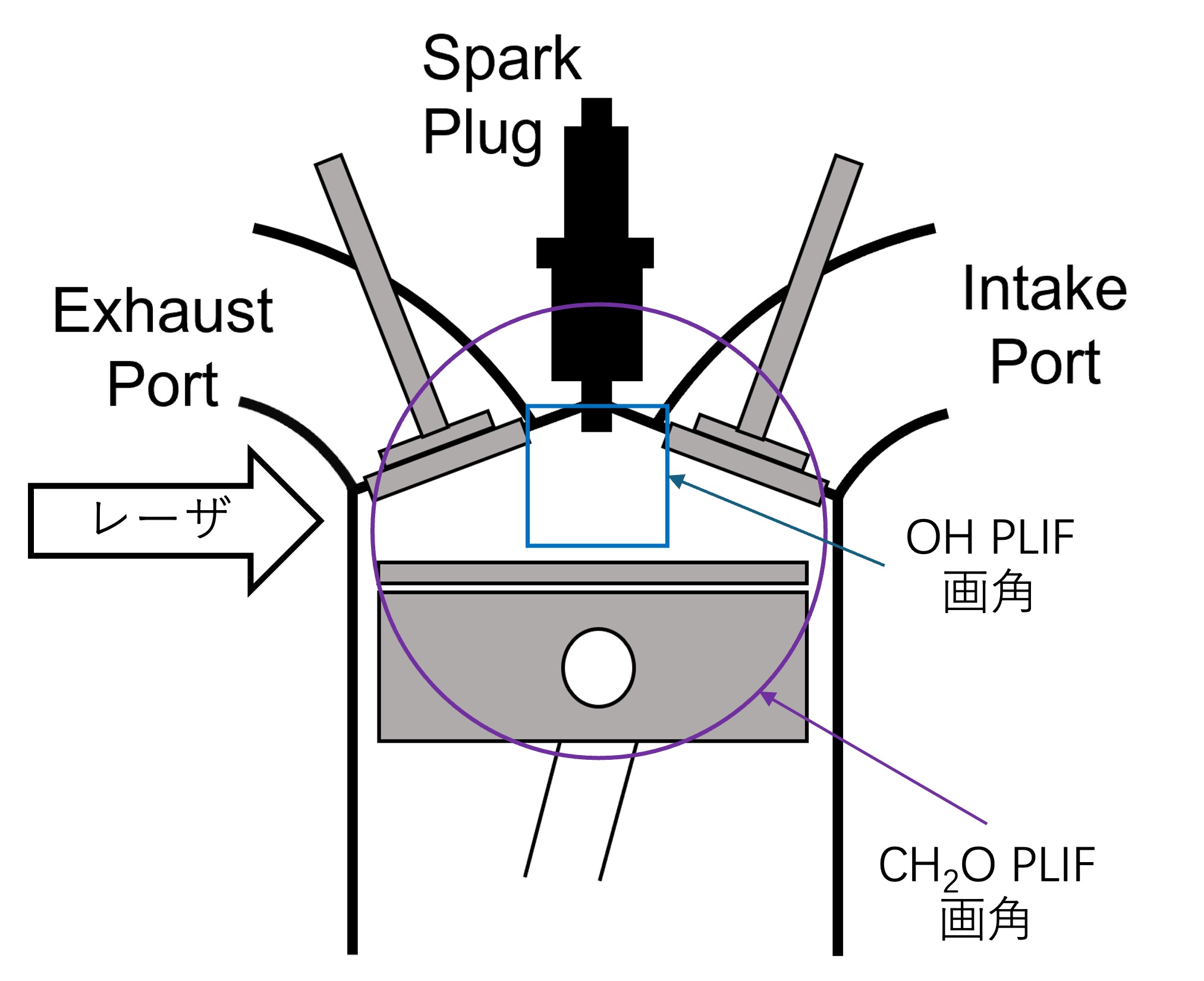
Relating fields of view to fluorescence distributions
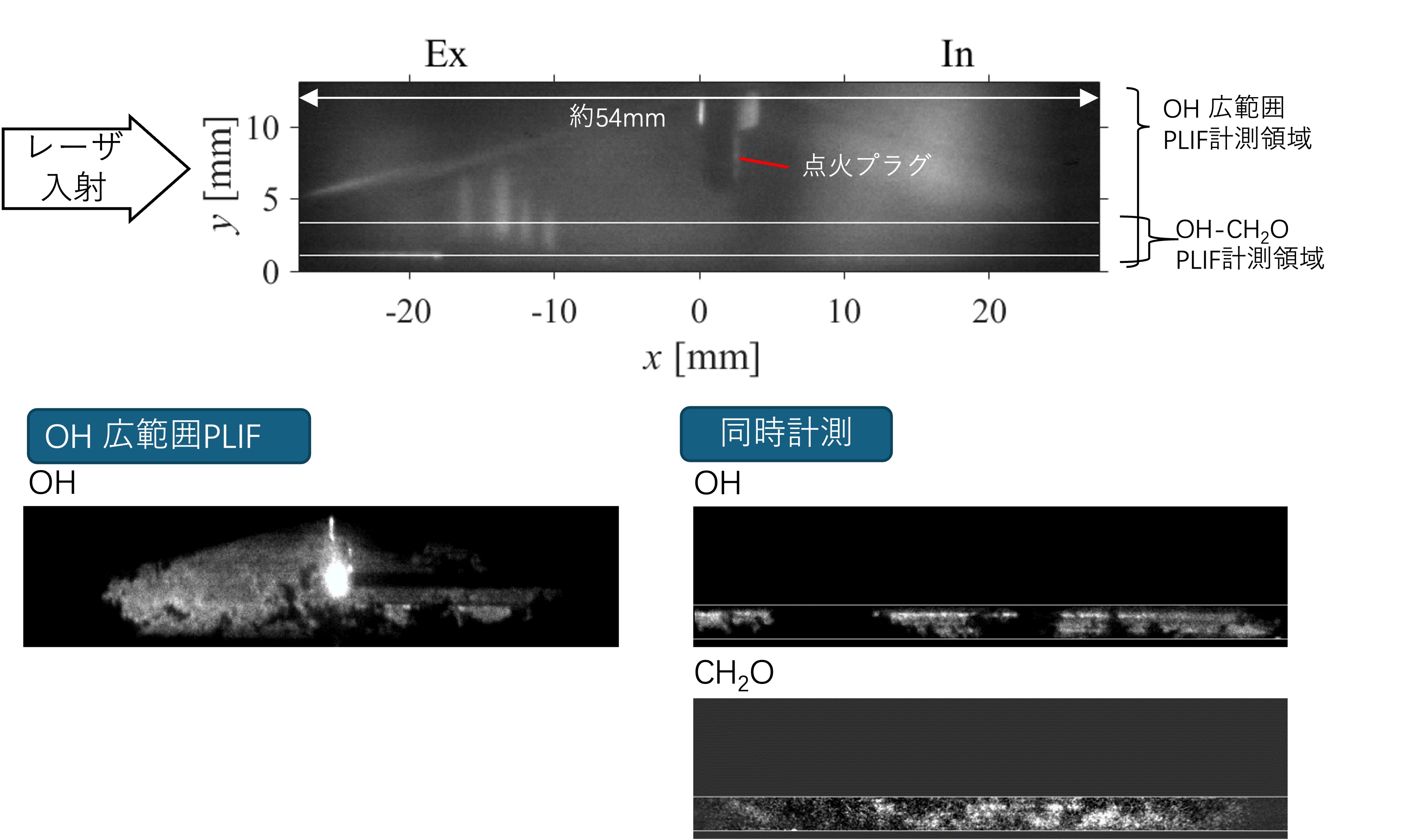
The field-of-view diagram identifies the OH and CH2O measurement regions, spark plug, and laser-entry direction. When fields of view or magnifications differ, distributions are compared over their common observation region.
The fluorescence distributions below show where each species signal appears and how far it extends. Signal intensity also depends on temperature and excitation and detection conditions, so brightness is interpreted together with distribution shape and spatial relationships, rather than as a direct measure of reaction intensity.
4. Connecting imaging to heat transfer
A thin-film MEMS sensor measures rapid heat transfer at the wall. Combined with OH/CH2O-PLIF, it helps investigate which features of local flow and flame structure govern heat flux as a flame approaches the wall.
Heat flux depends not only on flame arrival, but also on unburned-mixture temperature, near-wall velocity, flame-to-wall distance, and wall temperature. Synchronizing sensor response with the crank angle of PLIF images allows heat-transfer changes to be followed during flame approach, extinction, and reignition.
Placing image-derived flame positions and sensor heat-flux peaks on a common time axis helps evaluate heat-transfer increases associated with flame approach alongside the effects of flow-induced cooling and mixing. This supports a quantitative understanding of wall heat loss in the energy balance.
For devices such as tumble-enhancing plates, the aim is to establish flow and flame structures that stabilize combustion while limiting unnecessary wall heat loss. Separating the benefits of faster combustion from the cost of increased heat loss is essential for practical optimization.
5. From measurements to engine optimization
Acquiring flow, chemistry, pressure, and heat-transfer data on a common basis allows comparisons of equivalence ratio, ignition timing, and flow-control conditions. The results identify factors that improve combustion stability and thermal efficiency and provide validation data for simulations and reduced-order models.
For example, stronger tumble may accelerate early flame propagation, but increased near-wall velocity and flame approach can also raise heat loss, limiting the net efficiency gain. Our laboratory evaluates pressure-rise rate, combustion duration, cycle-to-cycle variation, and wall heat flux together to compare both burning rate and energy transfer.
Optical diagnostics provide an experimental framework connecting flow, reaction, and wall heat transfer to investigate the relationships governing engine performance. The resulting data support operating-condition optimization, combustion-chamber and flow-control component design, and future high-efficiency, low-emission combustion technologies.